Alright. Things are looking much better again. Moved the LNA to its rightful position just 2 m of LMR-195 behind the antenna. Put the FM BCB band stop filter behind the LNA. Since I’m not sending dc up the coax right now, and since the BCB stop filter is in the way anyway, I bit the bullet and built myself a quick and dirty solar charging battery supply for the LNA!
5 w solar panel, purchased a decade ago from Harbor Freight; 8 NiMH AA cells in a series holder; LM2596 buck converter to reduce the battery voltage to 5.0 v; a Tupperware container to hold the batteries and converter. Impressive, no? %^) Let’s see how it survives the night.
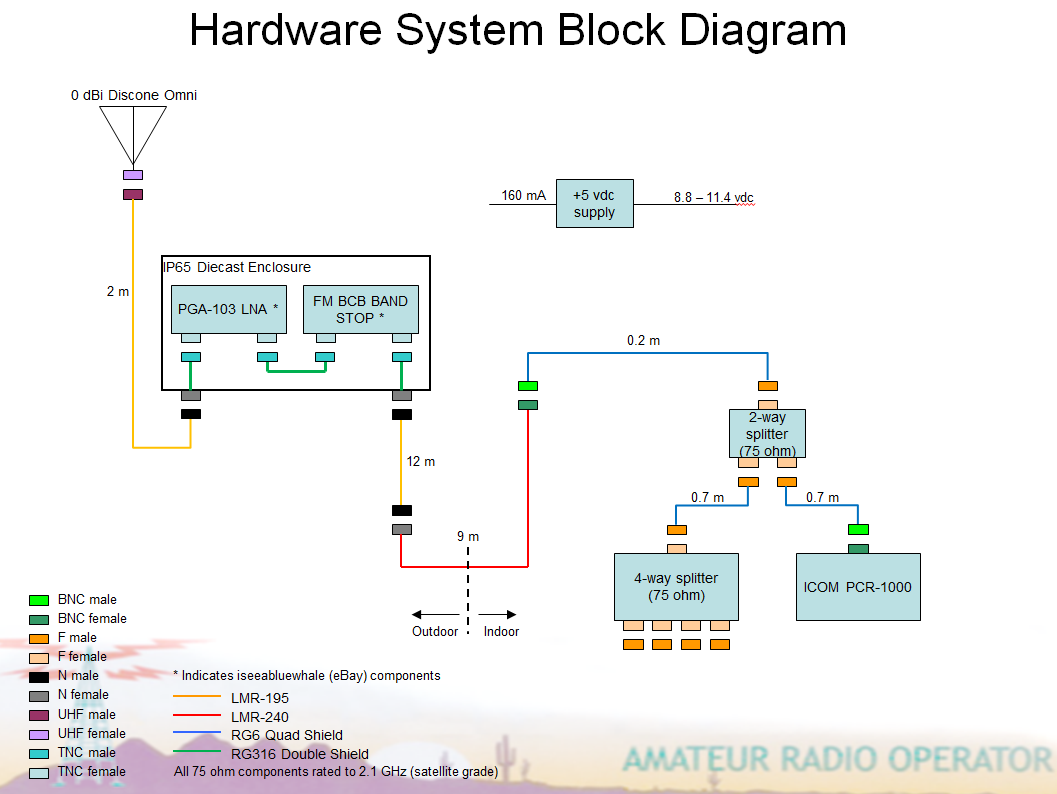
Here’s the new block diagram – note the PCR-1000 is on one leg of the first splitter, so it should have no more than about 4 dB additional loss than when directly connected to the coax from the roof.
001 – 100 MHz, w/LNA, w/filter, w/o-3dB-splitter:
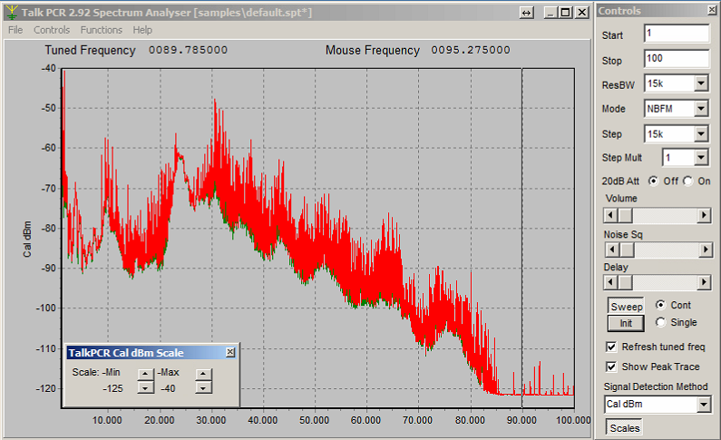
001 – 100 MHz, w/LNA, w/filter, w-3dB-splitter:
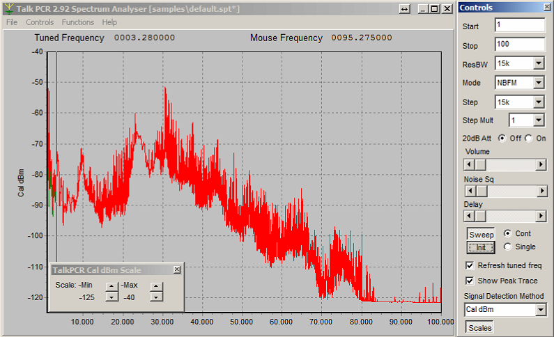
Here, the added loss from the splitter is apparent from DC to 80 MHz or so. It apparently doesn’t pass low frequencies well at all. Since the antenna is not rated that low anyway, it’s good to get rid of additional interfering signal…
100 – 200 MHz, w/LNA, w/filter, w/o-3dB-splitter:
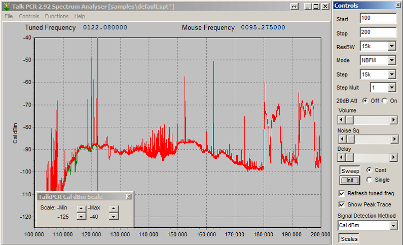
100 – 200 MHz, w/LNA, w/filter, w-3dB-splitter:
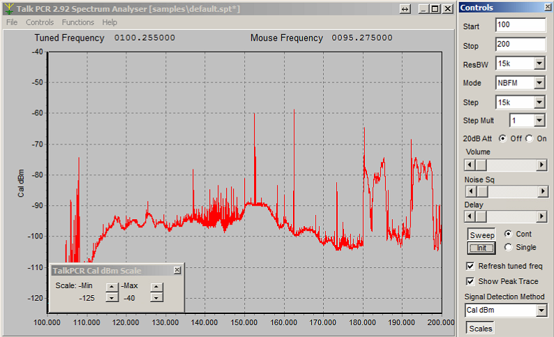
It seems that the splitter has greater than 3 dB additional loss until up around 140 MHz. The aviation band (118 – 136 MHz) is about 7 dB worse than without the splitter. But that’s it. No other weirdness. I can live with this.
Am much more satisfied now. LNA is directly behind antenna. Have a new experiment to see how solar battery charging works out.